Introduction
Components in aerospace, defense, and power generation must meet extreme strength requirements without excess weight or material waste. A bolt head in a jet engine, a coupling on a nuclear pressure vessel, or a drive shaft in a military vehicle cannot afford to fail—and the manufacturing method chosen plays a critical role in achieving that standard.
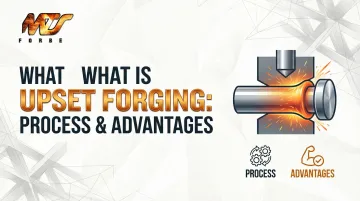
Upset forging — also called heading or upsetting — is a precision metalforming process that compresses metal axially to enlarge a localized cross-section, producing stronger, denser components than most other methods can achieve. This guide covers how the process works, what materials it suits, the advantages it offers, and how it compares to alternative forming methods.
Key Takeaways
- Upset forging compresses a metal billet along its axis to increase cross-sectional area, improving grain flow and strength
- Steps include controlled heating, die gripping, axial compression, and optional post-forging heat treatment
- Key advantages: superior strength, material efficiency, dimensional consistency, and high production throughput
- Common products include bolts, engine valves, flanges, drive shafts, couplings, and sucker rods
- Carbon steel, alloy steel, stainless steel, and high-nickel alloys are all compatible with the upset forging process
What Is Upset Forging?
Upset forging is a metalforming process that increases the cross-sectional diameter of a rod or bar by compressing it along its longitudinal axis. The term "upsetting" refers to the controlled reduction in length and expansion in diameter at the point where compressive force is applied. The alternate name "heading" originates from the process's historical use in forming bolt heads.
How Upset Forging Differs from Other Methods
Three common forging methods each take a different approach to shaping metal:
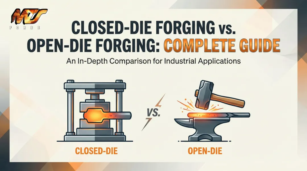
- Open-die forging shapes the whole workpiece freely between flat or simple-contoured dies
- Closed-die forging fills an enclosed cavity to produce complex three-dimensional shapes
- Upset forging concentrates deformation on a localized section of the bar
That last distinction matters. By targeting a specific zone, engineers control exactly where material is gathered and formed — which is what makes upset forging the right choice for fasteners, flanges, and shaft ends that need a larger diameter at a defined point.
Upset forging can be performed hot, warm, or cold depending on part requirements. Hot upset forging is most common for heavy industrial parts because elevated temperatures (typically 850°C to 1,250°C for steel) allow easier grain flow and reduce the force required to deform the material.
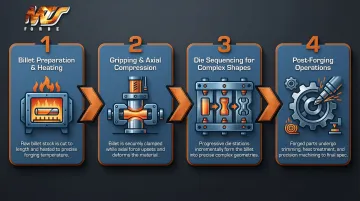
How the Upset Forging Process Works Step by Step
The upset forging sequence follows the same fundamental steps regardless of part geometry — though material selection and temperature targets vary considerably.
Billet Preparation and Heating
The process begins with selecting appropriate bar stock or billet cut to a precise length based on the final volume of metal needed. The billet is then heated until the metal is malleable but retains enough strength to hold its shape after deformation.
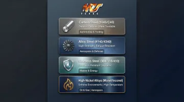
Target temperatures differ significantly by alloy:
| Material | Forging Temperature Range | Key Consideration |
|---|---|---|
| Carbon steel (1045/C45) | 850°C–1,100°C (1,562°F–2,012°F) | Standard hot forging window |
| Alloy steel (4140/4340) | up to 1,232°C (2,250°F) | Strict lower finishing limit to prevent grain boundary tearing |
| Stainless steel (304/316) | up to 1,260°C (2,300°F) | Higher temps required to maintain plasticity |
Gripping and Axial Compression (The Upsetting Stroke)
Once heated, the bar is clamped securely in gripping dies that hold it in place immediately behind the section to be upset. A heading tool or ram — horizontal or vertical — advances against the exposed end of the bar, applying controlled compressive force.
This causes the unsupported metal to "upset": shortening in length while expanding outward in diameter. The ram can be driven by mechanical or hydraulic presses depending on the required force and production volume. Adjustable press tonnage is a practical advantage here — matching force to the job means engineers can specify less expensive die material without sacrificing dimensional accuracy, which directly lowers tooling costs.
Die Sequencing for Complex Shapes
For parts requiring large or complex heads — such as flanged shafts or coupling ends — a single stroke is often insufficient. Engineers sequence progressively shaped dies, passing the billet through each station in turn to gather and redistribute material in stages. Reheating between stages may be necessary for very large upsets.
Critical Design Constraint (The 3d Rule): The unsupported length of bar (L) that can be upset in one stroke without risk of buckling must generally not exceed three times the bar diameter (3d). In practice, L is kept below 2.5d to ensure defect-free gathering. This constraint is fundamental to die planning and part design.
Post-Forging Operations
After the forging stroke, finishing steps include:
- Trimming flash if present
- Heat treatment (normalizing, quenching, tempering) to enhance final mechanical properties
- CNC machining or surface treatment to achieve final dimensional tolerances
MTS Forge handles tooling design, heat treatment, and finish machining under one roof — so parts arrive machined to final tolerances and inspection-ready, eliminating the coordination overhead of multiple vendors.
Key Advantages of Upset Forging
Upset forging's combination of localized deformation and grain refinement produces mechanical properties that machining or casting simply can't replicate.
Superior Strength via Refined Grain Structure
The compressive force during upsetting realigns the metal's grain flow to follow the contours of the part rather than cutting across them (as machining does). This directional grain flow significantly improves tensile strength, impact resistance, and fatigue life.
Research comparing forged steel to ductile cast iron found that forged steel exhibited 36% higher fatigue strength at 10^6 cycles, 52% higher yield strength, and 26% higher ultimate tensile strength—demonstrating the measurable mechanical advantage forging provides.
Material Efficiency and Cost Savings
Unlike machining from solid bar stock — which removes material as waste — upset forging forms the near-net shape by redistributing metal. This directly reduces raw material consumption and lowers per-unit cost, a meaningful advantage for medium-to-high volume production runs. MTS Forge's tooling inventory is built around this principle: making shapes rather than machining them from bar.
Dimensional Consistency and Repeatability
Once dies are set, every forged piece replicates the same geometry with tight tolerances, making upset forging ideal for OEM production where interchangeability is critical. Consistent grain structure across a batch also means predictable performance in the field.
High Production Throughput
Upset forging machines can be automated for high-volume output. High-speed hot formers can achieve up to 160 parts per minute (9,600 parts per hour) for smaller automotive components, while automated hot forging lines produce 240 to 360 parts per hour for larger fasteners.
Versatility Across Materials and Part Geometries
The process accommodates a wide range of metals—carbon steel, alloy steel, stainless steel, and high-nickel alloys like Monel and Inconel—and can produce everything from simple bolt heads to complex flanged shafts. That range is why the process shows up in aerospace structural components, defense hardware, energy flanges, and automotive fasteners alike — often where failure is not an option.
Typical Products Made by Upset Forging
Fasteners and Threaded Hardware
Bolts, screws, and studs use upsetting to create heads with continuous grain flow at the head-shank junction. This ensures maximum shear and fatigue resistance—essential for preventing catastrophic failures in aerospace and structural applications.
Structural Connectors
Flanges and couplings benefit from the concentric grain flow developed during gathering. The result is structural integrity under high pressure in power generation and petrochemical systems. MTS Forge produces upset forgings up to 26 inches in diameter and 1,500 pounds, suitable for demanding industrial applications.
Drivetrain and Engine Components
Engine valves, drive shaft ends, and connecting rod preforms are upset forged to withstand severe shock, impact, and cyclic loads. These components are common in automotive transmissions and aerospace propulsion systems.
Oilfield Components
Sucker rods feature hot-forged upset ends to accommodate threaded connections, providing the necessary strength for deep-well pumping systems operating in harsh environments.
Gear Blanks and Wheel Hubs
Special high-speed hot formers—a class of upset forging machines—produce axisymmetric round shapes such as gear blanks and wheel hubs at rates of 50 to 160 parts per minute. These near-net-shape preforms are subsequently machined into final gear forms for automotive transmission and engine components.
MTS Forge produces upset forgings for aerospace, defense, and power generation customers, with certifications including Mil I 45208 and Mil Q9858 to meet the traceability and quality requirements these industries demand.
Materials Suitable for Upset Forging
Most metals that can be hot forged can also be upset forged. The most commonly used material families include:
- Carbon steels (1045/C45): General-purpose shafts and structural parts; excellent response to heat treatment and reliable forgeability
- Alloy steels (4140, 4340): High-strength, high-fatigue applications in aerospace and defense — these grades require elevated forging temperatures but deliver exceptional mechanical properties
- Stainless steels (304, 316, 410): Corrosion-resistant components in marine, food, and energy environments — note that these grades require higher forging pressures than carbon steels
- High-nickel alloys (Monel, Inconel, Incoloy): Extreme-environment applications requiring corrosion resistance and high-temperature strength
Material Limitations
Copper cannot be electro-upset due to low electrical resistivity preventing adequate resistive heating. Highly brittle alloys (certain cast irons, high-carbon steels) are unsuitable for forging. Steels with high sulfur content can suffer from poor forgeability unless sulfide inclusions are controlled through specialized mill processing.
Material selection for upset forging should account for the intended post-forging heat treatment, the service environment (temperature, corrosion, cyclic loading), and the required degree of deformation. These variables interact in ways that aren't always obvious from a spec sheet alone, which is why partnering with a forge supplier who has genuine metallurgical expertise — not just process experience — reduces costly material selection errors before production begins.
Upset Forging vs. Other Forging Methods
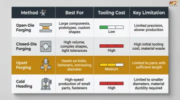
Upset Forging vs. Open-Die Forging
Open-die forging suits large, custom, or oversized parts where shape flexibility matters, but produces less dimensional precision and demands more post-machining. Upset forging excels when localized material gathering and consistent head geometry are required at volume.
Upset Forging vs. Closed-Die Forging
Closed-die forging can produce more complex three-dimensional shapes with excellent repeatability, but typically carries higher tooling costs and longer setup times. Upset forging offers lower tooling costs for axisymmetric parts (bolts, flanges, shaft ends) and is faster to set up for straightforward geometries.
The two methods are often used in sequence—upset forging to pre-form a shape, followed by closed-die finishing for complex details.
Upset Forging vs. Cold Heading
Both methods compress bar stock to form heads or flanges, but cold heading is performed at room temperature and is best for small, high-volume fasteners under approximately 25 mm diameter. Upset forging (typically hot or warm) is preferred when parts are larger, require tougher grain refinement, or involve alloy steels that need elevated temperatures to deform without cracking.
Quick Comparison
| Method | Best For | Tooling Cost | Limitations |
|---|---|---|---|
| Open-Die Forging | Large, custom, oversized parts | Low–Medium | Less dimensional precision; more post-machining |
| Closed-Die Forging | Complex 3D shapes at high repeatability | Higher | Longer setup times |
| Upset Forging | Axisymmetric parts (bolts, flanges, shaft ends) | Low–Medium | Best suited for localized geometry changes |
| Cold Heading | Small fasteners ≤25 mm at high volume | Low | Room temperature only; limited to smaller alloys |
Frequently Asked Questions
What is the upsetting process in forging?
Upsetting (also called heading) compresses a heated bar along its length to increase its cross-sectional area at a specific point. The bar is gripped in dies while a heading ram or punch applies axial force to the exposed end, causing it to expand in diameter.
What are the advantages of upset forging?
Upset forging produces a refined grain structure that follows part contours, improving strength and fatigue resistance by up to 36%. Near-net-shape forming minimizes material waste, and the process delivers dimensional consistency with predictable mechanical properties across high-volume production runs.
What are some of the typical products produced by upset forging operations?
Common examples include bolts, screws, engine valves, flanges, couplings, drive shaft ends, connecting rods, sucker rods, and gear blanks for automotive transmissions. Each requires a localized enlarged cross-section with strong, consistent mechanical properties.
What are the basic rules for die design for upset forging?
The key constraint is the 3d rule: unsupported bar length (L) must not exceed 3 times the bar diameter (d) in a single stroke to avoid buckling. In practice, L is kept below 2.5d. The maximum cross-section increase achievable in one stroke is approximately 1.5d.
What is the difference between cogging and upsetting?
Cogging is an open-die forging technique that reduces cross-sectional area and elongates a workpiece (working along the length). Upsetting does the opposite—it compresses length to increase cross-sectional area at a specific location.
What is an example of upset forging?
The bolt head is the classic example: the shaft is gripped in dies while the exposed end is compressed to form the larger-diameter head. Drive shaft ends follow the same principle—the shaft is held in the die cavity while the exposed end is upset to create a larger flange or coupling surface.