Introduction
Picture this: a refinery pipeline running at 900°F and 1,500 psi suddenly develops a leak at a joint connection. Within minutes, superheated steam fills the unit, forcing an emergency shutdown that costs hundreds of thousands of dollars per hour. The root cause? A flange specified at the wrong pressure class—a seemingly minor oversight with catastrophic consequences.
Flanges are the flat, circular components that create secure, leak-proof connections in piping systems across aerospace, power generation, oil and gas, and chemical processing. Despite how much depends on them, flange selection and manufacturing are poorly understood outside engineering circles.
This guide covers what a flange is, the main types used across industries, how connections are assembled to prevent failures, and the machining processes that determine whether a flange holds — or doesn't.
Key Takeaways
- Flanges are flat, circular components that create secure, leak-proof connections between pipes, valves, and equipment while allowing disassembly for maintenance
- Common types include weld neck (high-pressure use), slip-on (general low-cost applications), blind (system closure), threaded, socket weld, and lap joint flanges
- Connections depend on three elements: mating flange faces, a compressed gasket, and bolts tightened in a cross-pattern sequence
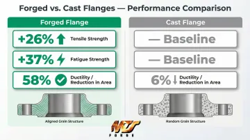
- Forged flanges deliver 26% higher tensile strength and 37% higher fatigue strength than cast equivalents due to aligned grain flow
- Production covers material selection, forging, CNC turning, face milling, bolt hole drilling, and rigorous inspection — with full traceability for critical applications
What Is a Flange?
A flange is a disc-shaped mechanical component used to connect and seal two sections of pipe, valve, pump, or equipment. Unlike permanent welded joints, flanges allow systems to be assembled, disassembled, inspected, and maintained without cutting or modifying the piping itself. That flexibility is what makes them essential anywhere routine maintenance or system modifications are part of normal operations.
Flange Anatomy
Every flange contains several critical features that define its function:
- Flange face — The precision-machined sealing surface where the gasket sits
- Bolt holes — Drilled at precise angular spacing around the bolt circle diameter (BCD) for mechanical fastening
- Bore — The inner diameter aligned with the pipe's inner diameter to maintain flow
- Hub — A tapered or raised section (on certain types like weld neck) that transitions stress from the flange to the pipe wall
Design variations in these elements determine each flange's suitability for specific pressure, temperature, and service conditions.
Where Flanges Are Essential
Flanges appear across nearly every industrial sector:
- Oil and gas processing and transmission
- Chemical and petrochemical plants
- Power generation (fossil fuel, nuclear, renewable)
- Aerospace (bleed air systems, hydraulic connections)
- Defense and naval systems
- Water and wastewater treatment
Each of these industries operates under strict performance requirements, which is why governing standards exist to define how flanges must be designed, rated, and tested. Key standards include ASME B16.5 (pipe flanges NPS 1/2 through 24), ASME B16.47 (large diameter flanges NPS 26 through 60), and API 6A (wellhead and high-pressure oil field equipment).
Common Types of Flanges
Flange type selection directly impacts system integrity. Installing the wrong type can cause stress concentration, chronic leakage, or catastrophic failure under pressure. Understanding each type's design and limitations is essential for engineers and procurement professionals.
Weld Neck Flange
Weld neck flanges are the preferred choice for high-pressure and high-temperature applications. The long tapered hub transitions smoothly from the flange to the pipe wall, distributing stress evenly across the joint and minimizing fatigue failure risk.
This geometry makes them the go-to selection in power generation, offshore oil and gas, refinery steam lines, and any system subject to thermal cycling or vibration.
When to specify: High-pressure systems (Class 600+), high-temperature service above 500°F, applications with cyclic loading or thermal expansion, and safety-critical systems in aerospace and nuclear.
Slip-On Flange
Slip-on flanges slide over the pipe end and are welded both internally and externally. They offer significant advantages: lower initial cost, easier installation with more forgiving alignment tolerances, and simpler fit-up compared to weld neck designs. However, their double fillet weld configuration creates stress concentration points that make them unsuitable for high-cycle fatigue environments.
When to specify: Low-to-moderate pressure systems (typically Class 150–300), non-critical utility lines, applications where ease of installation outweighs maximum strength, and systems without significant thermal cycling.
Blind Flange
Blind flanges are solid discs used to close off pipe ends or vessel openings. Despite appearing simple, they're subject to high bending stress at the center and must be rated for the same pressure class as the rest of the system. Common applications include pressure testing, isolating sections during maintenance, and creating future expansion points in piping systems.
Never assume a blind flange can be downrated because it's temporarily installed — pressure surges don't distinguish between permanent and temporary components.
Threaded and Socket Weld Flanges
Both threaded and socket weld flanges are common in small-diameter, high-pressure instrument and control piping (NPS 2 and smaller), but serve different installation constraints:
| Type | Connection Method | Best For | Limitation |
|---|---|---|---|
| Threaded | Screws onto pipe — no welding | Hazardous or explosive atmospheres; modifiable systems | Threads create stress concentration and potential leak paths |
| Socket Weld | Pipe inserts into recessed socket; single fillet weld | Higher strength than threaded; less precision than butt weld | Not suited for corrosive or very high-cycle fatigue service |
Lap Joint and Orifice Flanges
Lap joint flanges use a two-piece system: a stub end welded to the pipe and a loose backing flange that rotates freely. This design allows easy bolt hole alignment and is ideal for systems requiring frequent dismantling for inspection or cleaning — food processing and pharmaceutical applications are typical examples.
Orifice flanges feature radial pressure taps that accept instrumentation for flow measurement. They're critical in custody transfer metering (measuring flow at handoff points between parties), process control systems, and anywhere precise flow data is required. Per ASME B16.36, orifice flanges must be installed with correct orientation to ensure accurate readings.
How Does a Flange Connection Work?
Two flanges bolt together with a gasket compressed between their mating faces. Tightened bolts generate clamping force that compresses the gasket, creating a seal capable of containing system pressure. The flanges, gasket, and bolts function as an integrated engineered system — each element depends on the others performing correctly.
Understanding this is critical because 80% to 85% of gasket and flange joint failures are caused by improper installation, not manufacturing defects.
Gaskets: The Sealing Element
Gasket selection is driven by flange face type, system pressure and temperature, and the fluid or gas being sealed. Common gasket types include:
- Flat rubber or PTFE gaskets — For flat face flanges in low-pressure systems (water, air, non-corrosive fluids below 300°F)
- Spiral wound gaskets — Metal winding with filler material for raised face flanges in moderate-to-high pressure applications (steam, hydrocarbons, chemical service)
- Solid metal ring gaskets (RTJ) — Precision-machined rings for ring-type joint flanges in extreme pressure and temperature environments (Class 900+, subsea, wellhead)
Gasket failure modes include under-compression (insufficient bolt torque allows leakage), over-compression (crushing the gasket destroys its resilience), and improper material selection (gasket degrades chemically or thermally in service).
Flange Face Types
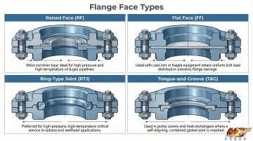
Flange face design determines gasket compatibility and sealing performance. The four standard face types are:
- Raised Face (RF) — The most common face type. The sealing surface sits 2mm (Classes 150/300) or 7mm (Classes 400+) above the bolting circle, concentrating gasket stress. Pairs with spiral-wound metal gaskets per ASME B16.20 for medium-to-high pressure/temperature service.
- Flat Face (FF) — Sealing surface is flush with the bolt circle. Used with low-pressure cast iron equipment and nonmetallic flat gaskets per ASME B16.21. Never bolt a flat face cast iron flange to a raised face steel flange — the unsupported gap causes brittle cast iron to fracture under bolt stress.
- Ring-Type Joint (RTJ) — A precision-machined groove accepts a solid metal ring gasket. This is the industry standard for extreme high-pressure and safety-critical applications (Class 900+, subsea wellheads, nuclear systems) per ASME B16.20 and API 6A.
- Tongue-and-Groove (T&G) / Male-and-Female (M&F) — One flange has a raised feature (tongue or male face); the mating flange has a matching recess. These designs improve alignment and confine the gasket, making them suitable for high-pressure hazardous fluid service.
Bolting and Torque
Bolts must be tightened in a cross-pattern (star) sequence, never in a circular order, to ensure even gasket compression across the entire joint. ASME PCC-1 guidelines specify a multi-pass approach:
- Hand-tighten all bolts first to seat the gasket evenly
- Apply torque in incremental passes using the star pattern
- Complete final-pass torque to the specified value for that flange class and gasket type
Insufficient torque causes leaks through under-compressed gaskets. Over-torque crushes gaskets, distorts flange faces, or breaks bolts. Each combination of pressure class, gasket type, and bolt size requires specific torque values — calculated or referenced from ASME PCC-1 tables, not estimated.
Pressure and Temperature Ratings
ASME defines pressure classes as 150, 300, 400, 600, 900, 1500, and 2500. These numbers represent the maximum allowable working pressure at a given temperature for a given material. Pressure rating decreases as temperature increases — a relationship that catches engineers off guard when equipment operates above its design baseline.
For example, per ASME B16.5:
- ASTM A105 Carbon Steel (Class 150): Rated for 285 psig at 100°F but only 170 psig at 500°F
- ASTM A182 F316 Stainless Steel (Class 600): Rated for 1,440 psig at 100°F but only 885 psig at 650°F
Selecting an incorrectly rated flange—such as installing a Class 150 component in a high-pressure steam line—is a primary cause of in-service failures. Always cross-check pressure-temperature tables for your specific material group before finalizing specifications.
The Flange Machining and Manufacturing Process
How a flange is manufactured—not just its design—determines grain structure, dimensional accuracy, mechanical strength, and long-term reliability. Flanges are produced through several manufacturing routes, and the choice of process significantly impacts cost, lead time, and performance.
Forging vs. Machining from Bar Stock
Forged flanges are produced by pressing or hammering heated metal into shape using dies. This process aligns the metal's grain flow to the contours of the finished part. Forged steel exhibits 26% higher tensile strength and 37% higher fatigue strength compared to cast equivalents, with ductility (reduction in area) of 58% versus just 6% for cast steel.
Machining flanges from bar stock removes material against the natural grain direction, creating potential weak points and wasting material. This approach is acceptable for low-pressure, non-critical applications but should never be used for high-cycle fatigue environments or safety-critical systems.
That difference in grain integrity is why closed die forging is the standard for demanding applications. MTS Forge uses closed die forging with a large tooling inventory to produce near-net-shape flanges up to 14 inches in diameter—reducing material waste and machining time while meeting the mechanical requirements of aerospace, defense, and commercial nuclear work.
Raw Material Preparation and Rough Machining
Manufacturing begins with material selection based on application requirements:
- Carbon steel (ASTM A105) — General-purpose, cost-effective, suitable for ambient and moderate-temperature service
- Stainless steel (ASTM A182 F316, F304) — Corrosion resistance for chemical processing, food service, marine environments
- Alloy steel — High-temperature or high-pressure service (power generation, refinery applications)
- Specialty alloys (Inconel, Monel, Incoloy) — Extreme environments with corrosive media or temperatures exceeding 1000°F
After material selection, blanks are cut to approximate size. Rough machining on a lathe or mill removes forging flash and excess material, establishing basic geometry.
CNC Turning and Face Milling
CNC turning creates the cylindrical shape, bore, and hub profile by spinning the workpiece against a cutting tool with micron-level precision. This establishes the flange's outer diameter, inner diameter (bore), and any hub transitions.
Face milling follows. The goal is a flat, smooth sealing surface held to tight flatness tolerances—typically 0.002–0.004 inches across the diameter. Surface finish here is not cosmetic; rough or wavy faces prevent proper gasket seating and cause chronic leakage.
Drilling, Tapping, and Grooving
Bolt holes are drilled at precise angular spacing around the bolt circle diameter per ASME or ANSI dimensional standards. Hole position tolerance is critical—misaligned holes between mating flanges cause installation difficulties and uneven gasket compression.
Tapping cuts internal threads in threaded flanges. Grooving machines the narrow precision groove in RTJ flanges that accepts the metal sealing ring. Both operations require precise positioning and depth control.
Inspection, Surface Finishing, and Quality Assurance
Once machining is complete, every flange goes through a defined inspection sequence before leaving the floor. Quality control includes:
- Dimensional inspection — Outer diameter, bore, bolt circle diameter, thickness, flatness
- Surface finish measurement — Verifying sealing face roughness meets specifications
- Non-destructive testing (NDT) — Magnetic particle inspection (ASTM E1444) detects surface cracks; ultrasonic testing (ASTM E213) detects internal voids and inclusions
For military, nuclear, and aerospace work, full material traceability is non-negotiable. MTS Forge holds certifications including Mil I 45208, NCA 3800, and Mil Q9858, with documentation maintained from raw material heat lot through final inspection—and for nuclear components, that record stays active for the life of the part.
Finished flanges may also receive surface treatments—anti-corrosion coatings or galvanizing—based on the service environment.
Choosing the Right Flange for Your Application
Flange selection is a system-level decision, not a component-level choice. Key variables include:
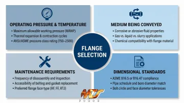
- Operating pressure and temperature: Always reference ASME pressure-temperature tables for your specific material. Ratings decrease as temperature increases, so pressure class must be confirmed at operating conditions—not ambient.
- Medium being conveyed: Corrosive fluids require stainless or specialty alloys. High-temperature steam calls for alloy steel. Food-grade or pharmaceutical service demands specific surface finishes and material certifications.
- Maintenance requirements: Systems requiring frequent disassembly favor lap joint or slip-on flanges. Weld neck flanges require cutting for removal, making them a poor choice where access is routine.
- Dimensional standards: Project specs may mandate ASME, API, DIN, or JIS standards. Confirm your flange matches the required standard and that all mating components are compatible.
Getting these variables right matters more than it might seem. Specification mismatches aren't just an inconvenience—they're a safety risk.
The Danger of Mismatched Specifications
A Class 150 flange installed in a high-pressure steam line can fail catastrophically, causing injury, equipment damage, and prolonged downtime. Similarly, bolting a flat face cast iron flange to a raised face steel flange creates stress concentration that fractures the brittle cast iron.
Cross-check pressure-temperature ratings, face type compatibility, gasket selection, and bolt specifications together as a system—not as individual components.
When to Specify Forged Flanges
Specify forged flanges (not cast or plate) for:
- High-cycle fatigue environments (thermal cycling, vibration, pressure fluctuation)
- Safety-critical systems (nuclear, defense, aerospace, subsea)
- Applications with extreme temperature swings where grain integrity matters
- Regulatory environments requiring material certification and production traceability
In these environments, verify that your supplier provides documented material traceability and a certified quality program. MTS Forge, for example, maintains certifications covering Mil I 45208, NCA 3800, and Mil Q9858—standards that govern commercial nuclear, aerospace, and defense work where forging integrity is non-negotiable.
Frequently Asked Questions
What is a flange in machining?
A flange is a flat circular rim used to connect pipes or equipment at joints. Creating one involves machining operations—facing, boring, drilling, and threading—to achieve the precise dimensions and surface finish required for a reliable seal.
What are the different types of flanges?
The most common types are weld neck, slip-on, blind, threaded, socket weld, lap joint, and orifice flanges. Each is designed for specific pressure ratings, installation methods, and service conditions, ranging from low-pressure utility systems to extreme high-pressure subsea applications.
How to properly torque a flange?
Hand-tighten bolts first, then torque in a cross-pattern (star sequence) across multiple passes to the manufacturer-specified value, typically derived from ASME PCC-1 guidelines. This ensures uniform gasket compression and a leak-free seal.
What are common flange installation mistakes?
The most frequent errors are:
- Using a circular instead of star bolt tightening sequence
- Wrong gasket type or material for the application
- Mismatched flange face types (FF assembled to RF)
- Overtorquing or undertorquing bolts
- Failing to inspect the flange face for damage or contamination before assembly
What materials are flanges commonly made from?
Common flange materials include carbon steel (ASTM A105) for general use, stainless steel (ASTM A182 F316, F304) for corrosion resistance, and alloy steel for high-temperature service. Specialty alloys like Inconel, Monel, or duplex stainless handle the most extreme environments.
What industries rely most on flanges?
Flanges are essential in oil and gas, power generation (including nuclear), chemical processing, aerospace, defense, shipbuilding, and water treatment—wherever piping systems must be connected, disassembled, and maintained reliably under pressure. The global flanges market is projected to reach $9.86 billion to $12.6 billion by 2034-2035, driven by energy infrastructure and industrial expansion.